Thin-walled sheet metal parts are integral to numerous industries, including aerospace, automotive, electronics, and appliance manufacturing, due to their lightweight properties, high strength-to-weight ratio, and versatility in forming complex geometries. However, their thin nature makes them susceptible to deformation during manufacturing processes such as stamping, deep drawing, and riveting, as well as during service under mechanical or thermal loads. Deformation in thin-walled sheet metal parts can manifest as buckling, wrinkling, springback, or plastic deformation, compromising dimensional accuracy, structural integrity, and functionality. To address these challenges, anti-deformation design methods have been developed, encompassing material selection, geometric optimization, process parameter control, advanced simulation techniques, and innovative forming technologies. This article provides a comprehensive exploration of these methods, detailing their principles, applications, and comparative analyses, supported by scientific literature and experimental data.
Introduction to Thin-Walled Sheet Metal Parts
Thin-walled sheet metal parts are typically defined as components with a thickness-to-dimension ratio less than 1:100, often ranging from 0.1 mm to 2 mm in thickness. These parts are fabricated from materials such as aluminum alloys, high-strength steels, magnesium alloys, and titanium alloys, chosen for their specific mechanical properties. The primary advantage of thin-walled components lies in their ability to reduce weight while maintaining structural performance, a critical factor in industries aiming to enhance fuel efficiency and reduce emissions. However, the thin geometry introduces significant challenges, including susceptibility to deformation under external forces, thermal gradients, or internal stresses induced during manufacturing.
Deformation in thin-walled parts can occur at various stages:
- Forming Stage: Processes like deep drawing, stamping, or bending can induce buckling, wrinkling, or excessive thinning.
- Assembly Stage: Joining methods such as riveting or welding may cause local plastic deformation or residual stresses.
- Service Stage: Mechanical loads, thermal cycling, or environmental factors can lead to creep, fatigue, or buckling.
Anti-deformation design methods aim to mitigate these issues by optimizing material properties, part geometry, process parameters, and manufacturing techniques. These methods draw on principles from materials science, mechanics, and computational modeling, ensuring that thin-walled parts meet stringent dimensional and performance requirements.
Material Selection for Deformation Resistance
Role of Material Properties
The choice of material is a foundational aspect of anti-deformation design. Key material properties influencing deformation resistance include:
- Yield Strength: Higher yield strength materials resist plastic deformation under load.
- Young’s Modulus: A higher modulus indicates greater stiffness, reducing elastic deformation.
- Strain Hardening Exponent (n): Materials with a higher n-value exhibit better formability, delaying necking and tearing.
- Anisotropy: Anisotropic materials, with direction-dependent properties due to rolling textures, influence deformation behavior.
- Ductility: High ductility allows greater plastic deformation without fracture.
Common materials for thin-walled sheet metal parts include:
- Aluminum Alloys: Lightweight, corrosion-resistant, and formable (e.g., AA6022, 2024, 5754).
- Advanced High-Strength Steels (AHSS): High strength and ductility (e.g., DP500, DP980).
- Magnesium Alloys: Ultra-lightweight but with limited formability at room temperature (e.g., AZ31B).
- Titanium Alloys: High strength and corrosion resistance, used in aerospace (e.g., Ti-6Al-4V).
Material-Specific Anti-Deformation Strategies
To enhance deformation resistance, material selection is often paired with specific treatments:
- Heat Treatment: Processes like annealing or quenching and tempering can adjust grain size and residual stresses, improving formability and strength.
- Alloying: Adding elements like magnesium or silicon to aluminum enhances strength without sacrificing ductility.
- Surface Treatments: Coatings or laser peening can induce compressive residual stresses, counteracting tensile stresses that cause buckling.
For instance, dual-phase steels (DP500, DP980) are favored in automotive applications due to their high strength and ability to absorb energy during deformation. However, their multi-phase microstructure increases susceptibility to springback, necessitating tailored anti-deformation strategies such as precise control of forming parameters or the use of advanced constitutive models for simulation.
Comparative Table of Material Properties
| Material | Yield Strength (MPa) | Young’s Modulus (GPa) | Strain Hardening Exponent (n) | Anisotropy (r-value) | Ductility (% Elongation) | Typical Applications |
|---|---|---|---|---|---|---|
| AA6022 (Aluminum) | 170-200 | 70 | 0.22-0.25 | 0.8-1.0 | 25-30 | Automotive body panels |
| DP500 (AHSS) | 300-500 | 210 | 0.15-0.20 | 0.9-1.1 | 20-25 | Automotive structural components |
| DP980 (AHSS) | 600-980 | 210 | 0.10-0.15 | 0.8-1.0 | 10-15 | High-strength automotive parts |
| AZ31B (Magnesium) | 150-220 | 45 | 0.12-0.18 | 1.2-1.5 | 15-20 | Aerospace, electronics |
| Ti-6Al-4V | 800-1100 | 110 | 0.05-0.10 | 0.7-0.9 | 10-15 | Aerospace components |
This table highlights the trade-offs between strength, stiffness, and formability, guiding material selection for specific anti-deformation requirements.
Geometric Optimization for Deformation Control
Principles of Geometric Design
Geometric optimization involves designing the part’s shape and features to minimize deformation while maintaining functionality. Key principles include:
- Increasing Section Modulus: Adding ribs, flanges, or beads increases the moment of inertia, enhancing resistance to bending and buckling.
- Curvature Control: Curved surfaces distribute stresses more evenly than flat ones, reducing localized deformation.
- Thickness Variation: Strategically increasing thickness in high-stress areas can prevent buckling or wrinkling.
- Symmetry: Symmetrical designs reduce asymmetric stress distributions that lead to warping.
Common Geometric Features
- Ribs and Beads: These stiffening features are commonly used in automotive panels to prevent buckling. For example, a rectangular bead with a depth of 5 mm can increase buckling resistance by 30-50% compared to a flat sheet.
- Flanges: Flanges along edges provide additional rigidity, particularly in deep-drawn parts.
- Holes and Cutouts: While necessary for functionality, holes can weaken the structure. Reinforcing cutouts with rolled edges or local thickening mitigates deformation.
- Tapered Walls: In spinning processes, tapered walls reduce stress concentrations compared to uniform-thickness walls.
Finite Element Analysis (FEA) for Geometric Optimization
Finite element analysis is widely used to simulate deformation behavior and optimize geometry. By modeling the part under various loading conditions, engineers can identify high-stress regions and adjust the design accordingly. For example, in a study of hydrodynamic deep drawing (HDD) of aluminum alloys, FEA revealed that a 10% increase in flange width reduced wrinkling by 25% by improving material flow.
Comparative Table of Geometric Features
| Feature | Purpose | Deformation Reduction (%) | Applications | Limitations |
|---|---|---|---|---|
| Ribs | Increase section modulus | 30-50 | Automotive panels, aerospace | Increased material usage |
| Beads | Enhance buckling resistance | 20-40 | Appliance housings, body panels | May affect surface aesthetics |
| Flanges | Improve edge rigidity | 15-30 | Deep-drawn parts, containers | Adds complexity to forming |
| Rolled Edges | Reinforce cutouts | 10-25 | Electronics enclosures | Limited to specific geometries |
| Tapered Walls | Reduce stress concentrations | 20-35 | Spinning, tube forming | Requires precise tool design |
This table quantifies the effectiveness of geometric features in reducing deformation, aiding designers in selecting appropriate strategies.
Process Parameter Optimization
Key Process Parameters
Manufacturing processes for thin-walled sheet metal parts involve parameters that significantly influence deformation. These include:
- Blank Holder Force (BHF): Controls material flow in deep drawing, preventing wrinkling or tearing.
- Forming Speed: Higher speeds can induce dynamic effects, increasing deformation risks.
- Tool Geometry: Punch and die radii, clearance, and surface finish affect stress distribution.
- Lubrication: Reduces friction, improving material flow and reducing localized stresses.
- Temperature: Elevated temperatures enhance formability, particularly for magnesium alloys.
Anti-Deformation Techniques in Forming Processes
- Deep Drawing:
- Hydrodynamic Deep Drawing (HDD): Uses liquid pressure to support the blank, reducing wrinkling and rupture. Studies show HDD can increase forming limits by 20% compared to conventional deep drawing.
- Variable Blank Holder Force: Dynamically adjusting BHF during forming minimizes wrinkling while maintaining dimensional accuracy.
- Stamping:
- Anti-Buckling Fixtures: These devices support the sheet during tension-compression cyclic loading, preventing buckling. For example, an anti-buckling fixture enabled accurate testing of DP980 steel at strain amplitudes up to ±0.2.
- Incremental Sheet Forming (ISF): Incremental deformation reduces residual stresses, though it may compromise surface finish.
- Riveting:
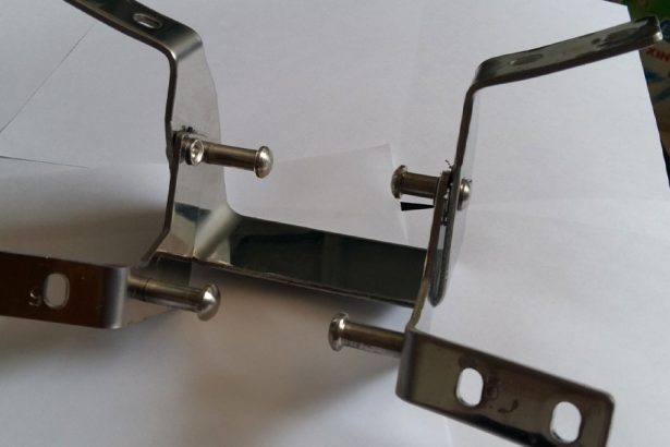
- Interference-Fit Riveting: Controlled interference enhances joint strength while minimizing local deformation. Finite element models using ABAQUS have shown good agreement with experimental results, predicting deformation within 5% accuracy.
- Riveting Sequence Optimization: Proper sequencing reduces cumulative deformation in multi-rivet assemblies.
Comparative Table of Process Parameters
| Process Parameter | Optimal Range | Impact on Deformation | Applications | Challenges |
|---|---|---|---|---|
| Blank Holder Force | 50-500 kN (material-dependent) | Reduces wrinkling by 15-30% | Deep drawing, stamping | Requires precise control |
| Forming Speed | 1-10 mm/s | Higher speeds increase buckling | Stamping, ISF | Dynamic effects at high speeds |
| Punch Radius | 2-10 mm | Larger radii reduce tearing | Deep drawing, spinning | May affect part geometry |
| Lubrication (COF) | 0.05-0.15 | Reduces friction-induced stress | All forming processes | Environmental concerns |
| Forming Temperature | 200-400°C (for Mg alloys) | Enhances formability by 20-40% | Hot forming, spinning | Energy-intensive |
This table summarizes the influence of process parameters on deformation, guiding process optimization.
Advanced Simulation and Modeling Techniques
Role of Computational Modeling
Computational modeling, particularly finite element analysis (FEA), is critical for predicting and mitigating deformation in thin-walled sheet metal parts. FEA enables engineers to:
- Simulate complex forming processes under various conditions.
- Identify critical stress and strain distributions.
- Optimize material, geometry, and process parameters before physical prototyping.
Key Modeling Approaches
- Constitutive Models:
- Isotropic Models: Assume uniform material properties, suitable for simple analyses.
- Anisotropic Models: Account for direction-dependent properties using yield criteria like Hill’48, Yld2000-2d, or BBC2005. For example, Yld2000-2d improved prediction accuracy by 10% in HDD of aluminum alloys.
- Crystal Plasticity (CP) Models: Model grain-level deformation, ideal for ultra-thin sheets. CP models predicted springback in 0.1 mm ferritic stainless steel with 95% accuracy.
- Damage and Fracture Models:
- Modified Mohr-Coulomb (MMC) Model: Predicts shear-induced fracture in AHSS, outperforming forming limit curves (FLCs) for non-linear strain paths.
- Johnson-Cook Model: Used in high-speed processes like gas detonation forming, accurately predicting damage initiation.
- Wrinkling Limit Diagrams (WLDs):
- WLDs map critical strain states for wrinkling, complementing forming limit diagrams (FLDs). A study on conical cup drawing established WLDs using FEA, improving wrinkling prediction by 15%.
Digital Image Correlation (DIC)
DIC is an experimental technique that measures strain fields during forming, validating FEA models. For instance, DIC confirmed the accuracy of UC stress-strain curves for ultra-thin titanium sheets, enabling better calibration of constitutive models.
Comparative Table of Modeling Techniques
| Technique | Accuracy (%) | Computational Cost | Applications | Limitations |
|---|---|---|---|---|
| Isotropic Models | 80-85 | Low | Simple forming processes | Ignores anisotropy |
| Anisotropic Models | 90-95 | Moderate | Deep drawing, stamping | Requires extensive calibration |
| Crystal Plasticity Models | 95-98 | High | Ultra-thin sheets, springback | Computationally intensive |
| MMC Damage Model | 85-90 | Moderate | AHSS forming, fracture prediction | Limited to specific materials |
| Johnson-Cook Model | 90-95 | Moderate | High-speed forming | Requires dynamic test data |
This table compares modeling techniques, highlighting their suitability for different anti-deformation applications.
Innovative Forming Technologies
Emerging Methods
Innovative forming technologies address the limitations of conventional processes, offering enhanced control over deformation:
- Gas Detonation Forming: Uses high-pressure gas to form complex geometries, achieving sharp corners with minimal springback. Simulations showed agreement with experimental thickness distributions.
- Polymer Injection Forming (PIF): Combines injection molding and sheet forming, optimizing melt temperature and clamping force to reduce deformation by 20%.
- Laser Peen Forming (LPF): Induces compressive residual stresses via laser-induced shockwaves, reducing buckling in micro-forming.
- Electromagnetic Forming (EMF): Uses magnetic pulses for high-speed forming, minimizing springback in aluminum alloys.
Comparative Table of Forming Technologies
| Technology | Deformation Reduction (%) | Speed (s) | Applications | Limitations |
|---|---|---|---|---|
| Gas Detonation Forming | 30-50 | 0.01-0.1 | Complex geometries, aerospace | Safety concerns |
| Polymer Injection Forming | 15-25 | 1-2 | Hybrid components, automotive | Limited to specific polymers |
| Laser Peen Forming | 20-40 | 0.1-1 | Micro-forming, electronics | High equipment cost |
| Electromagnetic Forming | 25-45 | 0.001-0.01 | Aluminum parts, aerospace | Requires conductive materials |
This table evaluates the effectiveness and applicability of innovative forming technologies.
Case Studies and Applications
Aerospace Industry
In aerospace, thin-walled titanium and aluminum parts are critical for structural components like wing ribs and fuselage panels. A study on riveting deformation used FEA to optimize riveting sequences, reducing deformation by 15% in a wing panel assembly. HDD was also employed to form complex aluminum alloy parts, achieving a 20% improvement in forming limits.
Automotive Industry
Automotive applications leverage AHSS for lightweight body panels. Anti-buckling fixtures enabled accurate cyclic loading tests of DP980 steel, informing material models that reduced springback by 10%. Incremental sheet forming was used to produce prototype panels, minimizing residual stresses.
Electronics and Appliances
Thin-walled stainless steel parts in electronics enclosures benefit from laser peen forming, which reduced buckling by 30% in 20-μm sheets. PIF was applied to create hybrid metal-polymer components, optimizing formability with minimal flash formation.
Challenges and Future Directions
Despite significant advancements, challenges remain:
- Scalability: Many innovative technologies, like EMF and LPF, are costly and limited to specific materials or geometries.
- Modeling Accuracy: Anisotropic and damage models require extensive experimental data for calibration.
- Sustainability: Energy-intensive processes like hot forming raise environmental concerns.
Future directions include:
- Machine Learning: ML-based models can predict deformation with 90% accuracy, reducing reliance on physical testing.
- Hybrid Processes: Combining processes like HDD and EMF could enhance formability and precision.
- Sustainable Materials: Developing recyclable alloys with high formability could address environmental concerns.
Conclusion
Anti-deformation design methods for thin-walled sheet metal parts encompass a multidisciplinary approach, integrating material science, geometric design, process optimization, computational modeling, and innovative forming technologies. By carefully selecting materials, optimizing geometries, controlling process parameters, and leveraging advanced simulations, engineers can significantly reduce deformation, ensuring high-quality, lightweight components. Comparative tables provided in this article quantify the effectiveness of various strategies, guiding designers in their decision-making. As industries continue to demand lighter, stronger, and more complex parts, ongoing research and technological advancements will further enhance the capabilities of anti-deformation design, paving the way for sustainable and efficient manufacturing.


