Feature modeling of sheet metal parts refers to a systematic approach in computer-aided design (CAD) and manufacturing (CAM) that leverages geometric and functional features to represent, design, and produce sheet metal components. This methodology integrates design intent, manufacturing constraints, and process planning into a unified framework, enabling engineers to create complex parts efficiently while ensuring manufacturability. Sheet metal, typically defined as metal formed into thin, flat pieces (less than 6 mm thick), is widely used across industries such as automotive, aerospace, electronics, and construction due to its versatility, strength-to-weight ratio, and cost-effectiveness. Feature modeling has emerged as a cornerstone of modern sheet metal engineering, bridging the gap between conceptual design and physical production through advanced computational techniques.
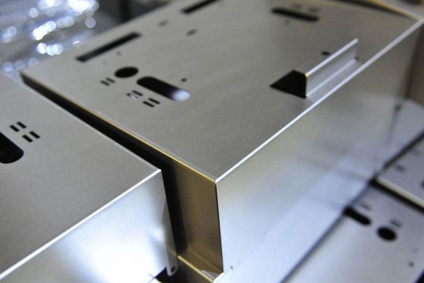
The concept of feature modeling originated in the broader field of solid modeling during the late 1970s and early 1980s, when CAD systems began transitioning from two-dimensional (2D) drafting to three-dimensional (3D) representations. Early CAD systems, such as those developed by companies like IBM and Dassault Systèmes, focused on basic geometric entities—lines, arcs, and surfaces. However, these systems lacked the ability to encapsulate higher-level engineering intent, such as the purpose of a hole or the manufacturability of a bend. Feature modeling addressed this limitation by defining “features” as discrete units of design that combine geometry with semantic information, such as tolerances, material properties, and manufacturing processes. For sheet metal parts, common features include bends, flanges, holes, hems, and embossments, each with specific rules governing their creation and interaction.
In the context of sheet metal, feature modeling gained prominence in the 1990s as industries sought to automate design-to-manufacturing workflows. Research by Wang and Bourne (1997) demonstrated the potential of feature-based systems to aid process planning and resolve manufacturability issues in sheet metal production. Their work introduced an integrated system where features were automatically generated during design and used to inform bending sequences and tooling decisions. This marked a shift from purely geometric modeling to a hybrid approach that incorporated manufacturing knowledge, laying the groundwork for subsequent advancements in the field.
The theoretical foundation of feature modeling rests on the principles of parametric design and knowledge-based engineering. Parametric design allows features to be defined with variables—such as bend radius, flange length, or material thickness—that can be adjusted dynamically, ensuring flexibility in design iterations. Knowledge-based engineering, meanwhile, embeds rules and constraints derived from manufacturing expertise into the modeling process. For instance, a bend feature might include a minimum radius constraint based on material ductility to prevent cracking, or a hole feature might enforce a minimum distance from an edge to avoid distortion during forming. These principles enable feature modeling to serve as a digital twin of the physical sheet metal part, capturing both its form and its fabrication requirements.
Historically, sheet metal design relied on manual drafting and empirical knowledge, with craftsmen using templates and physical prototypes to refine parts. The advent of numerical control (NC) machines in the 1950s and computer numerical control (CNC) in the 1970s revolutionized production, but design tools lagged behind. Early CAD systems, such as AutoCAD (introduced in 1982), improved drafting efficiency but offered limited support for 3D modeling or manufacturing integration. The introduction of feature-based CAD systems, such as Parametric Technology Corporation’s Pro/ENGINEER (now Creo) in 1987, marked a turning point. Pro/ENGINEER allowed engineers to define parts using features like extrusions and cuts, which could be adapted for sheet metal by incorporating bending and unfolding operations. This capability was further refined in the 1990s with dedicated sheet metal modules in software like SolidWorks (1995) and Autodesk Inventor (1999), which formalized feature modeling for sheet metal applications.
The research landscape of feature modeling for sheet metal parts can be divided into several key areas: feature recognition, feature classification, feature-based process planning, and integration with advanced manufacturing technologies. Feature recognition involves identifying and extracting features from existing CAD models, often using algorithms that analyze geometry and topology. For example, a 2020 study published in Scientific Reports introduced Sheet-metalNet, a deep learning-based system that employs a graph class-incremental learning strategy to recognize machining features in sheet metal parts. This approach outperformed traditional rule-based methods by handling complex intersecting features, demonstrating the power of artificial intelligence (AI) in modern feature modeling.
Feature classification, another critical research area, seeks to categorize sheet metal features based on their geometric and functional properties. A seminal work by Gupta and Gurumoorthy (2013) proposed a taxonomy dividing features into primary (e.g., walls, bends) and secondary (e.g., holes, notches) categories, with further subdivisions based on deformation type and manufacturing process. This classification aids in standardizing feature definitions across CAD platforms and facilitates interoperability between design and manufacturing systems. For instance, a bend feature might be subclassified as a “V-bend” or “U-bend,” each with distinct tooling requirements, while a hole might be designated as “punched” or “drilled,” influencing cost and precision.
Feature-based process planning leverages these recognized and classified features to automate the generation of manufacturing instructions. A 1997 paper in Robotics and Computer-Integrated Manufacturing by Wang and Bourne outlined a system where features like bends and flanges were used to determine optimal bending sequences, minimizing manufacturing costs and cycle times. The system also addressed feature interaction problems, such as overlapping bends or adjacent holes, by adjusting the design or process plan accordingly. This research has since evolved with the integration of finite element analysis (FEA) and simulation tools, which predict material behavior during forming and validate feature feasibility before production.
The application of feature modeling extends beyond traditional sheet metal forming to emerging technologies like additive manufacturing (AM) and incremental sheet forming (ISF). In AM, feature modeling supports the design of hybrid parts that combine sheet metal with 3D-printed components, as explored by Merklein et al. (2021) in Journal of Materials Processing Technology. Their study demonstrated how feature-based design enabled the creation of functional hybrid parts with improved strength and reduced weight, a critical advantage in aerospace applications. Similarly, ISF—a process where sheet metal is deformed incrementally using a single-point tool—benefits from feature modeling by defining deformation paths based on feature geometry, as noted in a 2020 review in MDPI’s Journal of Manufacturing and Materials Processing.
To illustrate the practical impact of feature modeling, consider its role in the automotive industry, where sheet metal parts like body panels and chassis components are ubiquitous. Feature modeling allows designers to specify features such as flanges for joining, embossments for stiffness, and holes for fasteners, while ensuring compatibility with stamping and welding processes. A case study from General Motors (circa 2005) highlighted how feature-based CAD reduced design-to-production time by 30% for a new vehicle model, as features were directly linked to CNC toolpaths and robotic assembly sequences. This efficiency stems from the ability of feature modeling to encode manufacturing constraints early in the design phase, reducing iterations and rework.
The aerospace sector offers another compelling example. Sheet metal parts in aircraft, such as wing skins and fuselage panels, must meet stringent tolerances and weight requirements. Feature modeling enables precise control over features like hems (to eliminate sharp edges) and joggles (to accommodate overlapping panels), as detailed in a 2020 ResearchGate paper on feature-based model difference identification. By semantically registering 3D CAD models based on feature intent, engineers can compare design iterations and identify changes—such as added or modified features—with engineering significance, enhancing quality control and documentation.
From a technical perspective, feature modeling relies on a combination of geometric algorithms, data structures, and user interfaces within CAD software. Geometric algorithms, such as boundary representation (B-rep) and constructive solid geometry (CSG), define the shape and connectivity of features. B-rep, widely used in modern CAD systems, represents a sheet metal part as a collection of faces, edges, and vertices, with features like bends modeled as curved surfaces joining planar regions. CSG, though less common for sheet metal, constructs parts by combining primitive shapes (e.g., cubes, cylinders) through Boolean operations, offering an alternative for conceptual design.
Data structures in feature modeling typically employ a feature tree or dependency graph, where each feature is a node linked to its geometric parameters and relationships with other features. For example, in SolidWorks, a sheet metal part’s feature tree might list a base flange, followed by a bend, a hole, and a hem, with each feature parametrically tied to the material thickness and K-factor (a measure of neutral axis shift during bending). This structure allows for rapid updates: changing the material thickness automatically adjusts all dependent features, ensuring consistency across the model.
User interfaces in CAD software enhance the accessibility of feature modeling by providing intuitive tools for feature creation and modification. In Autodesk Inventor, the “Sheet Metal” environment offers commands like “Flange,” “Bend,” and “Unfold,” each with dialog boxes for specifying parameters such as bend radius, angle, and relief type. These tools abstract the underlying mathematics, allowing engineers to focus on design intent rather than raw geometry. Advanced systems, such as Dassault Systèmes’ CATIA, integrate feature modeling with knowledge-based templates, enabling reuse of standardized features across projects.
The evolution of feature modeling has been shaped by both academic research and industry needs. Early efforts, such as those by Pratt and Regli (1997) in solid modeling, focused on feature recognition as a means to integrate CAD with CAM. Their work identified manufacturing features—like holes and slots—from 3D models, a capability later adapted for sheet metal to recognize bends and cuts. Subsequent research in the 2000s shifted toward automation and intelligence, with systems like the one proposed by Soman et al. (2003) using rule-based automation to generate sheet metal designs. These systems applied conditional loops to enforce design rules, such as maintaining a minimum bend radius, and foreshadowed the AI-driven approaches of today.
Modern feature modeling incorporates machine learning and deep learning to enhance recognition and planning. The Sheet-metalNet system (2020) exemplifies this trend, using a convolutional neural network (CNN) to analyze sheet metal CAD models and identify features with high accuracy, even in the presence of noise or incomplete data. This capability is particularly valuable for reverse engineering, where legacy parts are digitized and converted into feature-based models for redesign or reproduction. The SMCAD dataset, developed alongside Sheet-metalNet, provides a standardized benchmark for training such algorithms, addressing a previous gap in sheet metal-specific data.
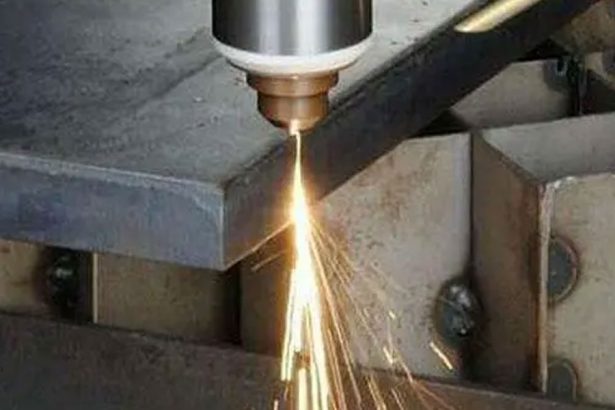
The practical applications of feature modeling are vast and varied. In HVAC (heating, ventilation, and air conditioning) systems, sheet metal ducts and fittings are designed with features like seams and collars, optimized for airflow and assembly. Feature modeling ensures that these components can be flattened into 2D patterns for cutting and folded accurately during fabrication, as noted in a 2023 Onshape tutorial on sheet metal design. Similarly, in consumer electronics, enclosures made from sheet metal use features like louvers (for ventilation) and tabs (for mounting), with feature modeling ensuring compatibility with laser cutting and press brake operations.
To compare different approaches to feature modeling, consider the following table, which evaluates traditional rule-based methods, parametric feature modeling, and AI-driven techniques based on key criteria:
| Approach | Accuracy | Automation Level | Complexity Handling | Computational Cost | Industry Adoption |
|---|---|---|---|---|---|
| Rule-Based | Moderate | Low | Low (struggles with intersecting features) | Low | High (early CAD systems) |
| Parametric Feature Modeling | High | Moderate | Moderate (handles standard features well) | Moderate | Very High (SolidWorks, Inventor) |
| AI-Driven (e.g., Sheet-metalNet) | Very High | High | High ( excels with complex features) | High | Emerging (research phase) |
This table highlights the trade-offs between approaches. Rule-based methods, prevalent in the 1980s and 1990s, rely on predefined logic and struggle with non-standard designs, making them less flexible. Parametric feature modeling, dominant since the late 1990s, balances accuracy and usability, making it the industry standard for sheet metal design. AI-driven methods, while computationally intensive, offer superior adaptability and are poised to transform the field as computing power and datasets improve.
Another comparison focuses on software tools commonly used for sheet metal feature modeling, assessing their capabilities and limitations:
| Software | Feature Support | Unfolding Accuracy | Integration with CAM | Learning Curve | Cost |
|---|---|---|---|---|---|
| SolidWorks | Extensive (bends, flanges, hems) | High | Strong (via add-ins) | Moderate | High |
| Autodesk Inventor | Comprehensive (includes joggles) | High | Moderate | Moderate | High |
| Onshape | Robust (cloud-based, multi-part) | High | Strong (via apps) | Low | Subscription-based |
| CATIA | Advanced (aerospace-focused) | Very High | Very Strong | High | Very High |
SolidWorks and Inventor dominate general-purpose sheet metal design, offering robust feature sets and reliable unfolding for flat patterns. Onshape, a cloud-native platform, excels in collaboration and ease of use, appealing to small teams and startups. CATIA, favored in aerospace, provides unparalleled precision and integration but requires significant expertise and investment.
The benefits of feature modeling are manifold. It reduces design time by automating repetitive tasks, such as generating bend tables or flat patterns, and improves accuracy by enforcing manufacturing constraints. It also enhances collaboration by providing a shared language of features that designers, engineers, and fabricators can understand. However, challenges remain. Complex feature interactions—such as a hole near a bend—can lead to unexpected deformations, requiring manual intervention or simulation. Additionally, the reliance on proprietary software limits interoperability, though standards like STEP (ISO 10303) mitigate this to some extent.
Future directions in feature modeling include greater integration with digital twins and Industry 4.0 paradigms. Digital twins—virtual replicas of physical parts—can use feature data to monitor real-time performance and predict maintenance needs, as explored in a 2021 study on smart manufacturing. AI and generative design, where algorithms propose optimal feature configurations based on constraints, are also gaining traction, promising to push the boundaries of sheet metal innovation. For instance, a generative design tool might suggest a novel embossment pattern to maximize stiffness while minimizing material use, guided by feature-based rules.
In conclusion, the research and application of feature modeling for sheet metal parts represent a dynamic and evolving field that combines engineering, computation, and manufacturing. From its roots in parametric CAD to its current frontier in AI-driven design, feature modeling has transformed how sheet metal components are conceived, produced, and utilized across industries. Its ability to encode design intent, streamline workflows, and adapt to new technologies ensures its continued relevance in the quest for efficient, sustainable, and high-performance manufacturing.


